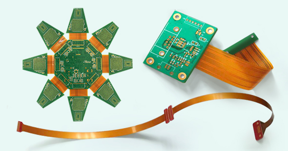
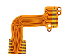
Flex PCB
Flexible circuits, also known as flex PCBs, are printed circuit boards that can be bent, twisted and folded because they have a substrate of flexible polyimide film and one or more thin layers of metallic material (usually copper). The copper layers are chemically etched to produce the desired circuit patterns. Adhesive is commonly used to bond the copper to the polyimide film, but other types of bonding can be used.
Flex PCBs use a coverlay for solder resist because regular soldermask has limited bendability. The coverlay is a sheet of polyimide that is glued to the surface of the flex circuit to protect the copper structure. Openings on the coverlay cannot be developed with photosensitive solder resist but must be created mechanically using drilling, routing or laser cutting.
Sometimes stiffeners need to be added to the flex circuits to harden areas of the boards where SMT and/or plated through hole components will be assembled. PCB stiffeners are usually made from FR4, Polyimide or aluminum. They are attached to the flexible circuits using thermal bonding or pressure-sensitive adhesives (PSA). Stiffeners can reinforce solder joints, increase abrasion resistance, relief strain and dissipate heat.
There are different kinds of flexible circuits, including single sided, double sided, multilayer and rigid flex circuits.
Single Sided Flexible Circuits
They consist of a layer of copper and a layer of dielectric material (flexible polyimide film) bounded together. A coverlay is added to the flex circuit for insulation and protection.
Double Sided Flexible Circuits
They consist of two layers of copper separated by a single layer of dielectric material. Plated through holes are used to make electrical connections between the two layers.
Multi-layer Flexible Circuits
They consist of three or more layers of copper separated by layers of dielectric material. Plated through holes are used to make electrical connections between the two layers.
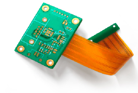
Rigid Flex PCB
Rigid-Flex Circuits
Are typically multilayer circuit boards that combine the best of both rigid boards and flexible circuits.
As illustrated in Figure 2, an area of the rigid flex board can be rigid and another area can be flex. A portion of the flexible circuit is buried inside the rigid section of the board.
The layers are interconnected through plated thru holes.
Benefits or advantages of Flex PCBs
- Unlike rigid printed circuit boards, flexible circuits can be bent, twisted, folded and shaped in countless configurations.
- They eliminate the need for mechanical connectors.
- In certain applications they may eliminate the need for wire harnesses thus reducing wiring errors.
- They are lighter and less bulky than rigid PCBs.
- They are best suited for harsh environments, they are waterproof and corrosion resistant.
- They are easy to install.
Disadvantages of Flex PCBs
- They are more costly to manufacture than rigid printed circuit boards.
- They are more difficult to assemble. Sometimes a special SMT fixture is required.
- They can be more easily damaged than rigid PCBs and they are very difficult to repair or rework.
When to use Flex Circuits
- Dynamic flexing of the circuit is needed
- A low number of device interconnects is needed
- Space and weight limitation
- High-shock and high-vibration environments
- High-temperature applications
- High-density applications
- High-reliability applications
Conclusion
Flex circuits offer a number advantages compared to rigid printed circuit boards. They have enable the development and implementation of new applications that were not achievable with rigid boards. Flex and rigid-flex PCBs have been proven in some of the most demanding applications including aerospace, military, and high-reliability medical devices. We encounter them in everyday life, in products such as smartphones, cameras, printers, tablets and laptops.
Before starting a new design it is important to do a costs and benefits analysis of using a flexible versus a rigid circuit. However, in some cases, the benefits of using a flexible circuit may not outweigh the cost manufacturing the PCBs.