Flexible circuits, also known as flex PCBs, are printed circuit boards that can be bent, twisted and folded because they have a substrate of flexible polyimide film and one or more thin layers of metallic material (usually copper). The copper layers are chemically etched to produce the desired circuit patterns. Adhesive is commonly used to bond the copper to the polyimide film, but other types of bonding can be used.
Flex PCBs use a coverlay for solder resist because regular soldermask has limited bendability. The coverlay is a sheet of polyimide that is glued to the surface of the flex circuit to protect the copper structure. Openings on the coverlay cannot be developed with photosensitive solder resist but must be created mechanically using drilling, routing or laser cutting.
Sometimes stiffeners need to be added to the flex circuits to harden areas of the boards where SMT and/or plated through hole components will be assembled. PCB stiffeners are usually made from FR4, Polyimide or aluminum. They are attached to the flexible circuits using thermal bonding or pressure-sensitive adhesives (PSA). Stiffeners can reinforce solder joints, increase abrasion resistance, relief strain and dissipate heat.
There are different kinds of flexible circuits, including single sided, double sided, multilayer and rigid flex circuits. Learn More...
Flex Circuits Stack-ups
SINGLE SIDED FLEX CIRCUITS
Consisting of a single thin conductive layer, hot-pressed and glued together with a flexible dielectric film to provide electrical insulation and protection from the elements, a single sided Flex PCB is the most basic and most common type of Flex Circuits.
DOUBLE SIDED FLEX CIRCUITS
Starting with a Polyimide film as a base layer, two separate conductive layers are then glued and hot-pressed together to both sides of the film. Plated Through Holes (PTH) are used to interconnect the copper layers, and additional layers of polyimide on both sides of the panel brings insulation to the double sided Flex Circuits.
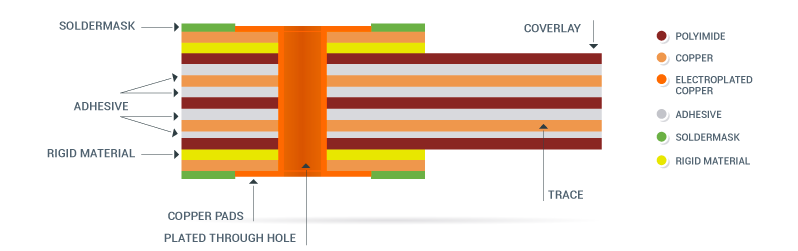
Containing three or more conductive layers, Multilayer Flex circuits manufacturing is performed combining double and single sided Flexible constructions, using adhesive layers to bond them together and interconnecting them by means of plated Vias. Circuit protection and electrical insulation is provided by a Coverlay (usually Polyimide).
Rigid-Flex Circuits are obtained by laminating together flexible and rigid substrates, providing the design not only with strength but with dynamic adaptability as well. The rigid parts are often used to carry components and the flex substrates serve as interconnection paths.
Materials
| Polyimide Films |
0.5 mil (.0005"), 1 mil (.001"), 2 mils (.002"), 3 mils (.003"), 5 mils (.005") |
| Polyester Films |
2 mils (.002") |
| Adhesiveless Base |
Polyimide: 0.5 mil (.0005") – 5 mils (.005") Copper: 0.5 oz. (.0007") – 2oz. (.0028") |
| Copper Foils |
0.5 oz. (.0007"), 1 oz. (.0014"), 2 oz. (.0028") |
| Adhesives |
Acrylic/Modified Acrylic, Phenolic Butyral, Modified Epoxy |
| Surface Finish |
Solder (hot air leveling or electrolytic plating), Electroless Au and Ni |
| Stiffeners |
FR-4, polyimide, metal, or customer supplied |
| Other Materials or Finishes |
Contact us at: support@pentalogix.com |
Capabilities
| Max. Panel Size |
250mm * 450mm |
| Layer Count |
0-6 |
| Minimum Trace Width/Spacing |
.003"/.003" (0.5 oz.)
.004"/.004" (1 oz.) |
| Minimum Trace to Route Edge Dimension |
+/-0.005" |
| Minimum Route Dimensional Tolerance |
+/-005" |
| Minimum Tolerance of ZIF Connector to Edge of Flex |
+/-003" |
| Minimum Feature to Feature Dimensional Tolerance |
+/-0.003" |
| Minimum Corner Route Radius |
0.010" +/-0.0005" |
| Minimum Inside Radius |
0.006" +/-0.0003" |
| Minimum Hole size |
+/-0.006" |
| Minimum Slot Width |
0.008" |
| Minimum Annular Ring Size |
0.014" |
| Minimum Space Between Coverlay Openings |
0.010" |
| Minimum Legend Line Width |
0.007" (preferred) |
| Edge of Coverlay Opening to Trace |
0.007" |
| Minimum Inner Diameter or Thermal Reliefs |
0.010" (drill size) |